
Vertical shaft impact crusher
Overview of Vertical Shaft Impact Crusher
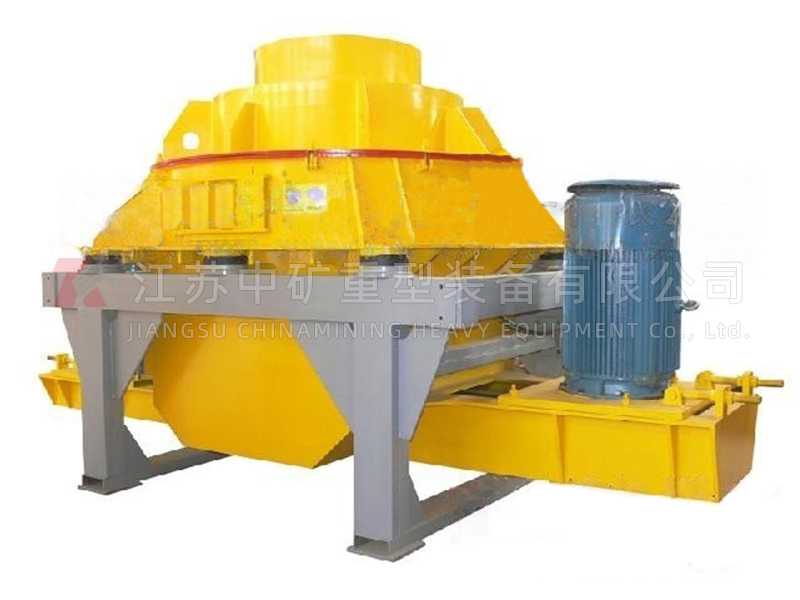
Vertical shaft impact crusher is a kind of crushing equipment developed based on the actual situation of sand production in China. The vertical shaft impact crusher is widely used for the medium and fine crushing (making sand particles) of various hard and brittle materials such as rocks, abrasive materials, refractory materials, cement clinker, quartz, iron ore and concrete aggregates. It is suitable for making sand and gravel used in construction and road construction and consists of seven parts including feed, distributor and vortex crushing chamber.
Working principle of vertical shaft impact crusher
Materials enter the crusher from the feeding hopper and are divided into two parts by the distributor. One part enters the high-speed rotating impeller from the middle of the distributor and is rapidly accelerated inside the impeller, with an acceleration of several hundred times the gravitational acceleration. They are then ejected from the three uniformly distributed flow channels of the impeller at a speed of 60-70 meters/second. Firstly, they collide and crush with part of the materials that fall from self collection around the distributor and then are impacted together to the material lining layer together in the vortex support chamber. Afterwards, they are rebounded by the material lining layer and impacted obliquely to the top of the vortex chamber so as to change their movement direction and deflect downwards. The materials emitted from the impeller flow channel form a continuous material curtain. This type of material is subjected to two or even multiple chances of impact, friction, grinding and crushing in the vortex crushing chamber. The crushed materials are discharged from the lower discharge port. Forming a closed circuit with a circulating screening system, the materials can generally be crushed into 20 meshes or less after three cycles. During the entire crushing process, the materials impact and crush with each other by themselves, not directly in contact with metal components, but rather through impact and friction with the material lining layer, resulting in reduced corner contamination and prolonged mechanical wear time. The clever self circulation of airflow inside the vortex chamber reduces dust pollution.
Technical Parameters
Model | (mm) Max. feed material | (Km) Power | (r/min) Impeller speed | (t/h) Processing capacity | (mm) External dimensions |
PCL-600B | 26 | 45-90 | 2000/2600 | 8-50 | 3500×1500×2050 |
PCL-900 | 30 | 990-150 | 1300/1700 | 55-120 | 3600×2140×2620 |
PCL-900B | 40 | 110-180 | 1000/1450 | 60-150 | 3600×2140×2620 |
PCL-1250 | 50 | 220-360 | 950/1200 | 100-280 | 4520×2640×3100 |
PCL-1350 | 60 | 320-440 | 800/1200 | 160-360 | 5500×2785×3030 |