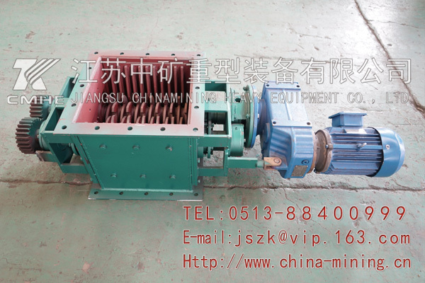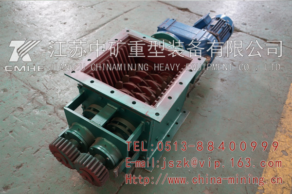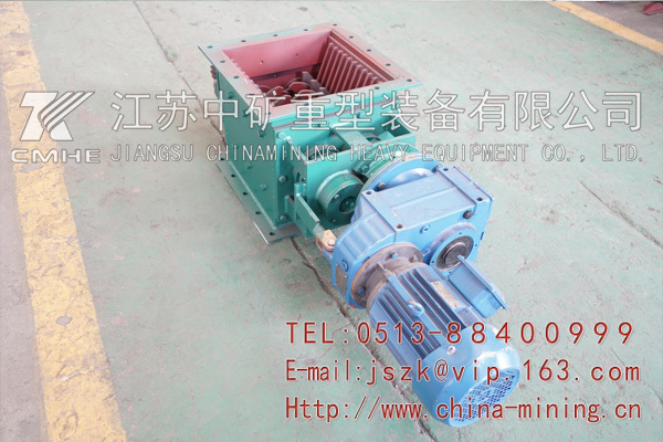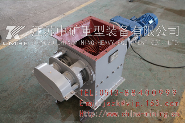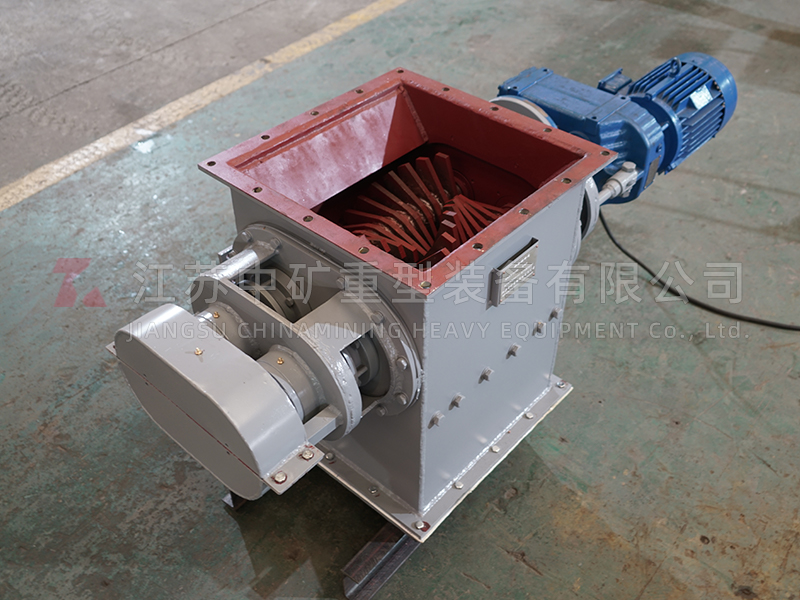
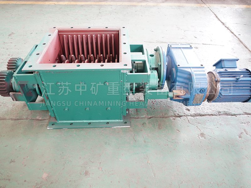
Crushing valve
The main function of the crushing valve is to crush the blocks in the material flow of the discharge device, which are formed by the material being damp in the warehouse or storehouse. Due to the inability of the blocks in the material to pass through the discharge port of the unloader, it can cause material blockage and cause false signals of non-real flow rate of the flow control valve. In mild cases, it can affect the normal production of the process system, while in severe cases, it can cause serious imbalance between the raw material and fuel due to false signals, resulting in ultra high temperature in the combustion equipment and even equipment accidents. The crushing valve can be installed horizontally or vertically at the feeding end of the unloading equipment at the discharge outlet, such as the front of the flow regulating valve or pneumatic cut-off valve. When large blocks of material appear in some materials, they can be immediately crushed to prevent them from blocking the channel of the discharge valve and ensure smooth discharge. The rotor of the crushing valve is equipped with radially-arranged crushing claws, which move the block material through the grid and crush it. The operational safety of the crushing valve is ensured by the integrated motor speed detection device in the electric control box. When certain block materials in the material cannot be crushed and the rotor gets stuck, the speed detection device will alarm and automatically reverse, pushing away the block materials that cannot be crushed before proceeding with forward rotation. When both forward and reverse rotations are blocked, the crushing valve will automatically stop and wait for the fault to be resolved before running. The speed detection device is an optional device, and this requirement needs to be specified when ordering the equipment.
Design Features
The maximum model's throughput can reach 1000m3/h.
Suitable for various gasification chutes and storage discharge outlets
Designed for logistics temperatures up to 120 degrees Celsius
Low energy consumption, with a drive motor power of only 1.1KW (for specifications below B400) and 1.5KW (for specifications above B500) at 25 rpm
High wear-resistant materials are used for crushing claws and grid plates
Simple maintenance
Integrated speed detection device (optional)
When selecting an integrated speed detection device, an electronic control box is randomly equipped.
Parameter Table for Installation of Crushing Valve
Model | Effective cross-sectional size | Capacity (m3/h)* | Size of bulk material(mm) | Speed (rpm) | Power (kW) | Fluidization pressure(kPa) | Air consumption (m3/min) |
KPS250 | B250 | 200 | <150mm | 24-26 | 1.1 | ≥30 | 0.19 |
KPS300 | B300 | 300 | <150mm | 24-26 | 1.1 | ≥30 | 0.23 |
KPS315 | B315 | 325 | <150mm | 24-26 | 1.1 | ≥30 | 0.24 |
KPS350 | B350 | 375 | <150mm | 24-26 | 1.1 | ≥30 | 0.26 |
KPS400 | B400 | 450 | <200mm | 24-26 | 3 | ≥30 | 0.30 |
KPS500 | B500 | 600 | <200mm | 24-26 | 4 | ≥30 | 0.38 |
KPS600 | B600 | 800 | <200mm | 24-26 | 5.5 | ≥30 | 0.45 |
KPS630 | B630 | 900 | <200mm | 24-26 | 5.5 | ≥30 | 0.47 |
KPS650 | B650 | 900 | <200mm | 24-26 | 7.5 | ≥30 | 0.57 |
KPS700 | B700 | 900 | <200mm | 24-26 | 11 | ≥30 | 0.69 |
KPS800 | B800 | 900 | <200mm | 24-26 | 11 | ≥30 | 0.73 |