
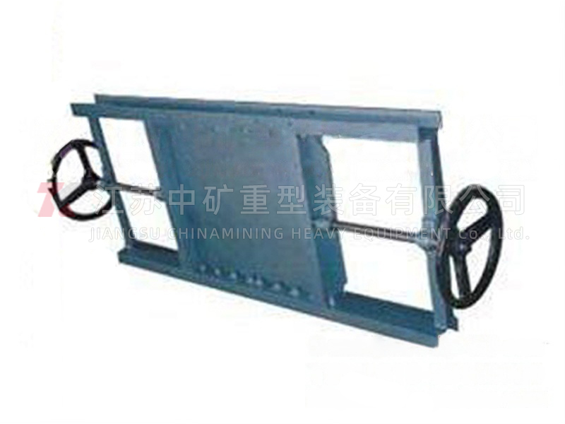
WCF-Z/X material conditioning gate (air delivery chute shut-off valve)
Material adjustment gate is a kind of adjustment and cut-off gate developed by our company according to the requirements of pneumatic conveying working conditions. It is widely used in pneumatic conveying systems in building materials, metallurgy, mining, light industry, glass and other industries.
Structural features:
The material adjustment gate is welded with high-quality carbon steel and is divided into upper and lower channels. The lower channel is an inflatable layer, the upper channel is a material conveying layer, and the middle is an air permeable layer. The spiral gate can be adjusted arbitrarily, especially for dry powder without viscosity, fine particles, etc. It has the characteristics of low energy consumption, no noise, no pollution, less maintenance, no blocking, convenient operation and long service life.
Performance parameters
| Inflation pressure | Gas consumption | Water content | Applicable media |
| 0.005~0.01MPa | ≈ 0.13~0.26m3/min | <1% | Cement raw materials, cement finished products, talcum powder, bauxite, etc. |
Working principle:
The material regulating gate is inflated by the fan with low pressure and small capacity air through the inflation layer of the lower channel air inlet. The gas is uniformly blown upward through the boiling plate, encouraging the material to move upward. When the material falls under its own weight, the equipment installation inclination produces displacement, which repeatedly causes the material to move forward. The regulating gate is composed of screw gate and sealing pair, etc., and the screw rod is driven to rotate by manual rotation hand wheel, so that the gate can be adjusted or cut off arbitrarily with the displacement of the screw rod.
Instructions for use:
Before installation, please check whether there is any debris attached to the inner cavity of the gate, and whether the boiling plate is damp. If the boiling plate is damp, please replace it before installation, otherwise the use effect will be affected. Check whether each transmission part is flexible and reliable. The bolts shall be tightened evenly after sealing gasket is added for connection between flanges. When debugging, manually rotate the hand wheel, clockwise rotation is off, otherwise it is on, and there is no blocking phenomenon in operation.
WCF outline:
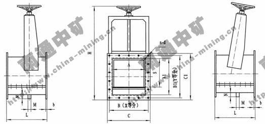
WCF_Z/X Contour Connection Dimension
| A | A1 | B | B1 | C | C1 | X | Y | N-d | L | B | N | M | H | S |
| 200 | 340 | 250 | 390 | 290 | 430 | 3 | 6 | 18-Φ10 | 300 | 8 | 40 | G1/2" | 900 | 265 |
| 250 | 390 | 300 | 440 | 340 | 480 | 3 | 6 | 18-Φ10 | 300 | 8 | 40 | G1/2" | 1000 | 315 |
| 300 | 440 | 350 | 490 | 390 | 530 | 4 | 7 | 22-Φ10 | 300 | 8 | 40 | G1/2" | 1100 | 365 |
| 350 | 490 | 400 | 540 | 440 | 580 | 4 | 7 | 22-Φ10 | 300 | 8 | 40 | G1/2" | 1200 | 415 |
| 400 | 540 | 450 | 585 | 490 | 630 | 5 | 8 | 26-Φ14 | 300 | 10 | 40 | G1/2" | 1300 | 465 |
| 450 | 600 | 500 | 635 | 540 | 690 | 5 | 8 | 26-Φ14 | 400 | 10 | 40 | G1" | 1400 | |
| 500 | 640 | 552 | 693 | 600 | 740 | 6 | 9 | 30-Φ14 | 400 | 10 | 45 | G1" | 1500 | 565 |
| 550 | 690 | 600 | 743 | 650 | 790 | 6 | 9 | 30-Φ14 | 400 | 10 | 45 | G1" | 1600 | |
| 600 | 740 | 650 | 795 | 700 | 840 | 7 | 10 | 34-Φ14 | 400 | 12 | 45 | G1" | 1700 | |
| 650 | 790 | 700 | 845 | 750 | 890 | 7 | 10 | 34-Φ14 | 400 | 12 | 45 | G1" | 1800 |
Ordering instructions:
When selecting and ordering, please refer to the product sample and indicate the product specifications, models and technical parameters (operating temperature, equipment conditions, medium properties, etc.).
The specifications listed in the table are for special media or other special requirements. Please contact our distribution department and technical department to design and manufacture separately for you.